
Modern motorcycles run tight electrical systems. Manufacturers size the wiring for factory loads only. So when riders bolt on auxiliary LEDs, heated gear, GPS units, and USB chargers, problems start fast when using a motorcycle auxiliary light wiring diagram.
Most stock handlebar switches cannot safely carry extra lighting current for years. The switch contacts wear down. Resistance increases. Heat builds. Eventually the switch fails. Sometimes the wiring melts first.
That problem gets worse on modern CAN bus motorcycles. Sensitive control modules monitor voltage constantly. A sloppy lighting install can trigger faults, battery drain, or charging instability.
This is where a relay earns its place.
A relay acts like an electrically controlled heavy-duty switch. Your handlebar switch activates the relay coil with a tiny current draw. Then the relay itself handles the heavier current load directly from the battery. The lights receive stable voltage. The stock wiring stays protected.
A proper install also improves LED performance. Voltage drop kills light output. Thin factory wiring often starves auxiliary lights under load. A relay-fed circuit delivers cleaner power and brighter output.
This guide breaks down every part of the process. You will learn relay anatomy, fuse sizing, grounding strategy, wire routing, ignition-trigger integration, and troubleshooting. You will also see how a proper motorcycle auxiliary light wiring diagram prevents overheating, flickering, and electrical chaos on the road.
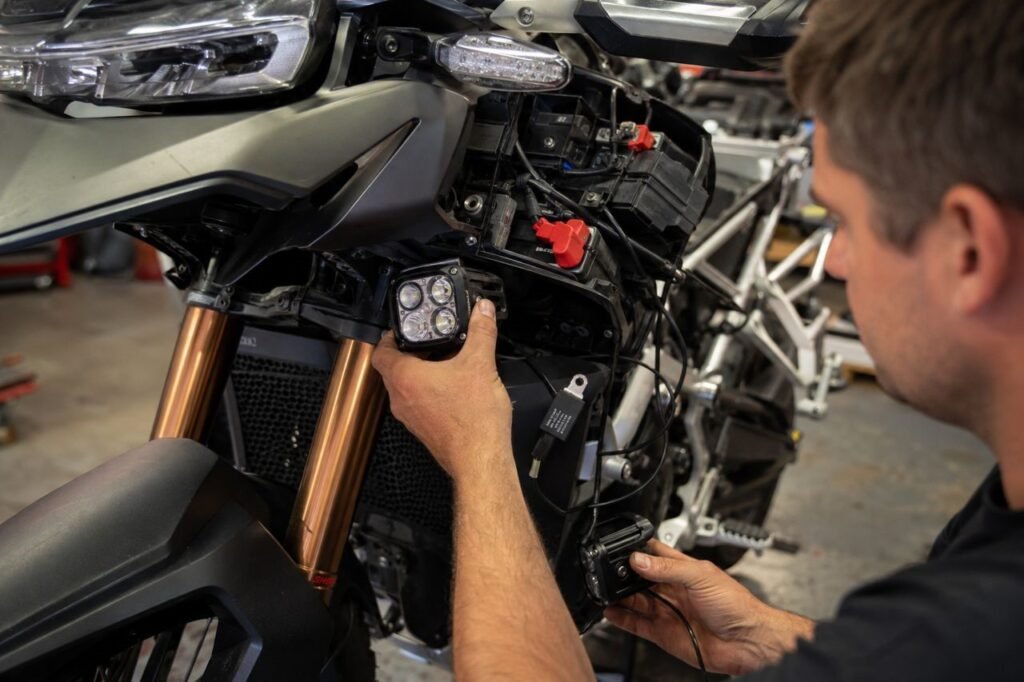
Why LEDs Actually Need a Relay
Many riders ask: do LED auxiliary lights need a relay?
Technically, not always. Realistically, yes.
LEDs draw less current than halogen lights. A typical 55-watt halogen auxiliary light pulls around 4.5 amps at 12 volts. A modern 20-watt LED pod may pull only 1.6 amps.
That lower current fools riders into thinking direct wiring is safe.
The problem is not just total amperage.
Motorcycle switches use tiny copper contacts. Every time current passes through those contacts, microscopic arcing occurs. Over time, resistance builds. Heat increases. Voltage drops. Eventually the switch becomes unreliable.
LED drivers also react badly to unstable voltage. Cheap wiring creates spikes and drops during engine rev changes. That causes flickering, shortened driver lifespan, or intermittent shutdowns.
A relay isolates the sensitive switch circuit from the heavier lighting circuit. The switch only activates the relay coil, which usually draws less than 0.2 amps.
That means:
- Less heat inside factory switches
- Lower voltage drop
- Better LED brightness
- Longer wiring lifespan
- Reduced risk of melted connectors
A proper motorcycle auxiliary light wiring diagram also protects the charging system from accidental overloads. Specifically on smaller bikes with stators producing under 350 watts, efficient power distribution matters.
So while LEDs consume less power, the relay still protects the motorcycle’s electrical system long term.
4-Pin vs. 5-Pin Relays
Most motorcycle lighting installs use either a 4-pin SPST relay or a 5-pin SPDT relay.
Here is the difference.
| Feature | 4-Pin SPST Relay | 5-Pin SPDT Relay |
|---|---|---|
| Contact Configuration | Single output | Dual-path output |
| Common Pins | 30, 85, 86, 87 | 30, 85, 86, 87, 87a |
| Normal State | Open circuit | Open and closed paths |
| Ideal Use Case | Auxiliary lights | Switching between circuits |
| Number of Accessories Controlled | One primary load | Two separate states |
| Complexity | Simple | Moderate |
| Reliability | Excellent | Good |
| Best Choice for LED Pods | Yes | Usually unnecessary |
Most riders only need a 4-pin relay.
That setup appears in nearly every reliable motorcycle auxiliary light wiring diagram because it stays simple and durable.
A 5-pin relay becomes useful when switching between low-power and high-power lighting modes or integrating advanced control logic.
For standard auxiliary LEDs, stick with a 4-pin relay unless the build specifically requires switched outputs.
Anatomy of a 12V Motorcycle Relay
A relay looks simple outside. Inside, it contains a small electromagnetic switch assembly.
Understanding the internals matters because it helps diagnose failures later.
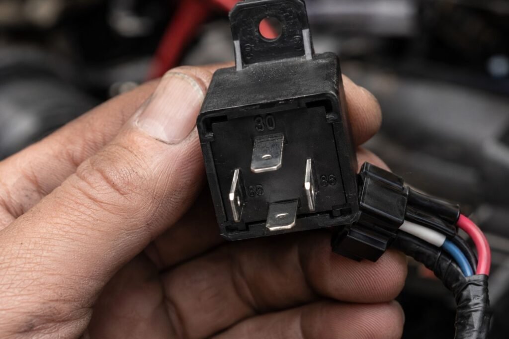
A standard relay has four key terminals:
- Pin 30 — Main battery power input
- Pin 85 — Coil ground
- Pin 86 — Coil trigger power
- Pin 87 — Power output to lights
A basic 4 pin relay wiring diagram motorcycle lights setup always revolves around those four terminals.
Inside the relay sits a copper coil wrapped around an iron core. When current flows through Pins 85 and 86, the coil creates a magnetic field.
That magnetic field pulls a spring-loaded metal arm inward.
Once the arm moves, it physically connects Pin 30 to Pin 87.
Now battery power flows directly to the lights.
When the switch turns off, the magnetic field disappears. The spring pushes the arm back. The connection opens again.
This mechanical separation protects delicate switches from heavy current flow.
Most quality relays handle 30 or 40 amps safely. Your switch never sees that load because the relay absorbs it.
That is the backbone of every professional motorcycle auxiliary light wiring diagram used on touring bikes, ADV machines, and dual sports.
The Comprehensive Master Installation Guide
Now comes the real work.
This section explains exactly how to wire 12v relay for auxiliary lights using professional workshop practices.
Tools and Materials
Use quality components. Cheap electrical parts fail fast on motorcycles because of vibration and moisture.
You need:
- 4-pin 12V automotive relay
- Inline waterproof fuse holder
- 14 AWG wire for lighting load
- 18 AWG wire for trigger circuit
- Heat-shrink tubing
- Crimp connectors
- Ratcheting crimper
- Wire loom
- Multimeter
- Ring terminals
- Waterproof switch
- Dielectric grease
If using a prebuilt motorcycle LED pod light wiring harness, still inspect the wire gauge before installation. Many budget harnesses use undersized wire.
Step 1: Disconnect the Battery
Always remove the negative battery terminal first.
Never work on live motorcycle wiring.
One accidental frame short can destroy a fuse block or ECU instantly.
Step 2: Mount the Relay
Mount the relay close to the battery but away from engine heat.
Under the seat works well on most motorcycles.
Keep the relay upright if possible. This reduces water intrusion risk.
Step 3: Install the Main Power Wire
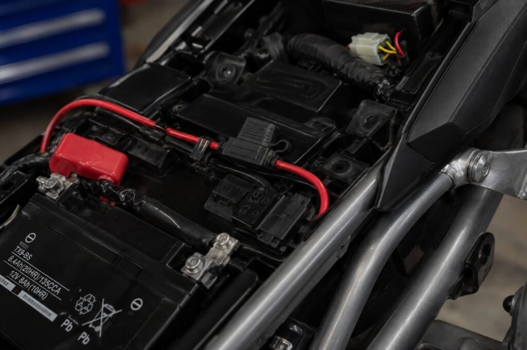
Run a 14 AWG wire from the positive battery terminal to Pin 30.
Install the fuse holder within six inches of the battery terminal.
This matters.
If a short develops before the fuse, the entire wire becomes a heating element.
Most dual LED pod setups need a 10-amp fuse. Larger systems may require 15 amps.
Never oversize the fuse.
A fuse protects the wire, not the accessory.
Step 4: Wire the Lights
Run another 14 AWG wire from Pin 87 to the positive lead on the auxiliary lights.
If running two pods, split the circuit evenly with a soldered junction or waterproof distribution block.
Avoid cheap plastic T-taps.
They loosen under vibration.
A professional motorcycle auxiliary light wiring diagram always shows direct crimped or soldered connections.
Step 5: Ground the Lights
Ground each light individually.
Do not daisy-chain grounds between pods.
You can ground directly to the battery negative or a verified frame ground point.
Bare metal contact matters.
Painted frame sections create resistance.
Apply dielectric grease after tightening to prevent corrosion.
Step 6: Wire the Trigger Circuit
Now wire the relay control side.
Connect Pin 85 to ground using 18 AWG wire.
Connect Pin 86 to your switch output wire.
The switch itself receives power from a switched ignition source. More on that later.
At this stage, the relay activates only when the switch sends low-current power to the coil.
This setup follows the classic 4 pin relay wiring diagram motorcycle lights configuration used in professional motorsport wiring.
Step 7: Route the Wiring Correctly
Bad routing destroys wiring fast.
Never run lighting wires near:
- Exhaust headers
- Radiators
- Steering stops
- Chain paths
- Sharp subframe edges
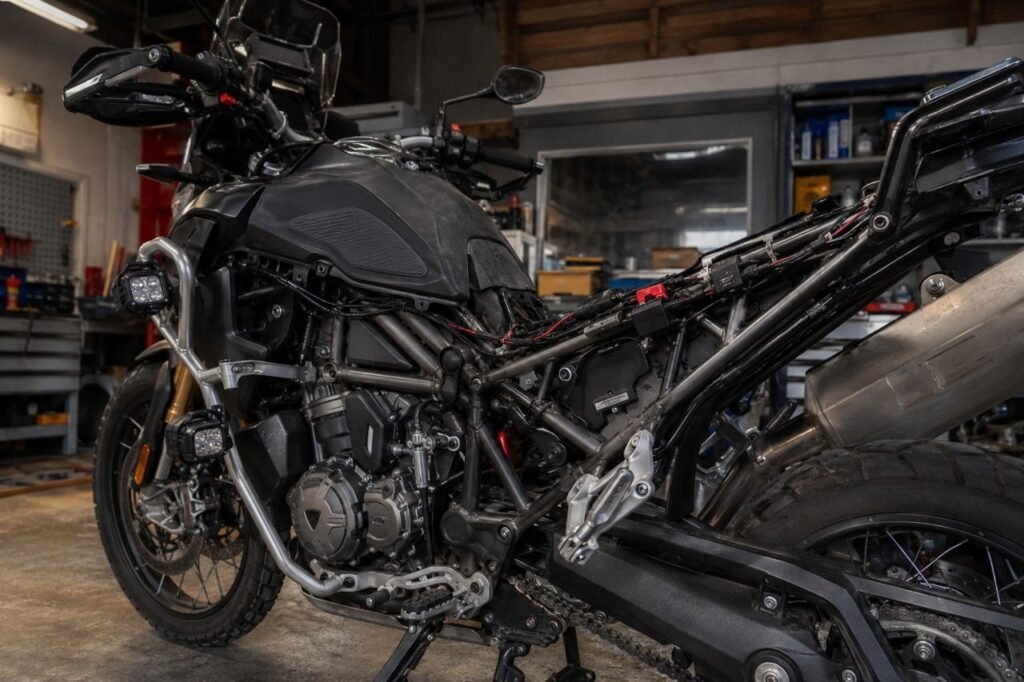
Follow the factory harness whenever possible.
Use zip ties every few inches.
Leave enough slack at the handlebars for full steering movement.
Specifically check for pinch points near the tank and steering neck.
Heat-shrink all exposed connectors.
Then wrap the harness in split loom for abrasion protection.
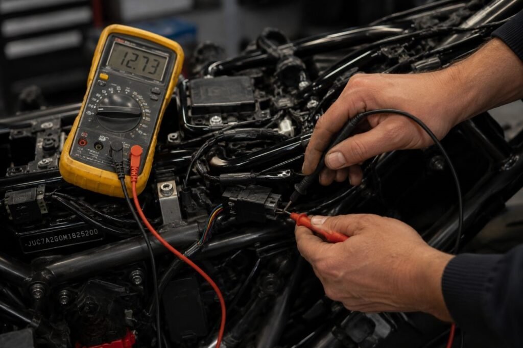
Step 8: Test Voltage
Reconnect the battery.
Start the motorcycle.
Measure voltage at the lights with a multimeter.
You want voltage within 0.3 volts of battery voltage.
Large drops indicate poor grounds or weak crimps.
A quality motorcycle auxiliary light wiring diagram minimizes voltage loss by using short, thick wiring paths.
Step 9: Waterproof the System
Motorcycles live outdoors.
Seal every connector possible.
Use adhesive-lined marine heat-shrink tubing.
Apply dielectric grease inside relay terminals and switch connectors.
Most lighting failures come from water intrusion, not overload.
The Ignition Switch Tie-In
Many riders ask how to wire motorcycle lights to ignition switch correctly.
This step prevents dead batteries.
If the relay trigger wire connects directly to battery power, the lights can stay on with the key removed.
That drains the battery fast.
Instead, locate a switched 12V source.
Good options include:
- License plate light wire
- Running light wire
- Tail light power wire
- Accessory circuit output
Use a multimeter.
Turn the key on.
Check for 12 volts.
Turn the key off.
Voltage should disappear completely.
That wire becomes the trigger source for your auxiliary light switch.
So the relay only activates when the ignition stays on.
Avoid tapping into ECU communication lines or CAN bus data wires. Modern motorcycles often use sensitive multiplexed systems.
If unsure, use a dedicated fuse block with ignition-trigger capability.
A proper motorcycle auxiliary light wiring diagram always isolates accessory loads from sensitive factory electronics.
Troubleshooting & The Hyperflash Fix
One common problem appears after LED conversions.
The turn signals blink extremely fast.
This issue happens because factory flasher relays expect higher resistance from incandescent bulbs. LEDs draw much less current, so the system thinks a bulb failed.
That leads riders to search for how to fix LED hyperflash on motorcycle setups.
You have two main solutions.
Inline Load Resistors
Resistors simulate incandescent bulb load.
They install parallel to the LED signals.
This method works but creates heat.
Mount resistors away from plastic fairings or wiring.
Electronic LED Flasher Relay
This is the better solution.
Replace the stock thermal flasher with an electronic LED-compatible unit.
Electronic relays flash consistently regardless of load.
They run cooler and waste less energy.
If auxiliary lights flicker during engine revs, check:
- Weak grounds
- Undersized wire
- Loose crimp terminals
- Charging voltage instability
Most issues trace back to poor grounding or cheap connectors.
A clean motorcycle auxiliary light wiring diagram helps eliminate those failures before they start.
Frequently Asked Questions
What wire gauge should I use for motorcycle auxiliary lights?
Use 14 AWG wire for the main lighting circuit. Use 18 AWG for the relay trigger and switch wiring. Larger high-output systems may need 12 AWG.
What fuse size works best for LED pod lights?
Calculate total wattage divided by system voltage. Two 20-watt LED pods draw roughly 3.3 amps at 12 volts. A 5-amp fuse works well there. Most riders safely use 10 amps for future expansion.
Should I ground auxiliary lights to the frame or battery?
Battery negative gives the cleanest ground path. Frame grounding also works if the contact point uses bare metal with zero corrosion or paint contamination.
Can I install a motorcycle LED pod light wiring harness instead of building my own?
Yes, but inspect the quality first. Many cheap harnesses use thin wire, weak relays, and poor waterproofing. Replace questionable terminals immediately.
A professionally built motorcycle auxiliary light wiring diagram paired with quality components will outlast most budget harness kits by years.